- After the cross section has been selected, the width of the stream is
determined. A tag line or measuring tape is strung at right angles across the
measurement section for measurements made by wading, from a boat, or from an
unmarked bridge.
|
|
Measurement of stream width with a measuring
tape. |
- Next the spacing of the verticals is determined to provide about 25 to 30
subsections. The verticals should be so spaced that no subsection has more than
10 percent (ideally 5 percent) of the total discharge.
|
| Definition sketch of midsection method of
computing cross-section area for discharge measurements.
|
- After all items listed above have been done, the measurement note sheets for
recording observations are prepared. The following information will be recorded
for each discharge measurement:
|
- Name of stream and location to correctly identify the established gauging
station; or name of stream and exact location of site for a miscellaneous
measurement.
- Date, party, type of meter suspension, and meter number.
- Time measurement was started using military time (24-hr clock system)
- Bank of stream that was the starting point.
- Control conditions.
- Gauge heights and corresponding times.
- Water temperature.
- Other pertinent information regarding the accuracy of the discharge
measurement and conditions which might affect the stage-discharge relation.
|
|
Discharge measurement note (9-275-F). |
- After the note sheet is readied, the meter assembly is checked. The meter
should balance on the hanger and should spin freely; the electric circuit
through the meter should operate satisfactorily; and the stopwatch should check
satisfactorily in a comparison with the hydrographer's watch. After recording on
the note sheet the station (distance from initial point) of the edge of water,
the actual measurement is ready to be started.
|
- Depth (if any) at the edge of water is measured and recorded. The depth
determines the method of velocity measurement to be used, normally the two-point
method or the 0.6-depth method (See below).
|
- After the meter is placed at the proper depth and pointed into the current,
the rotation of the rotor is permitted to become adjusted to the speed of the
current before the velocity observation is started.
|
- Then the number of revolutions made by the rotor is counted for a period of
40 to 70 s. The stopwatch is started simultaneously with the first signal or
click, which is counted as "zero," and not "one."
|
- The stopwatch is stopped on a convenient number coinciding with one of those
given in the column headings of the meter rating table and is read to the
nearest second. The number of seconds and the number of revolutions are then
recorded.
|
- The hydrographer moves to each of the observation verticals and repeats the
above procedure until the entire cross section has been traversed.
|
|
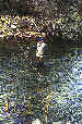
Current-meter measurements by wading |
- Current-meter measurements are best made by wading, if conditions permit.
Wading measurements have a distinct advantage over measurements made from
cableways or bridges in that it is usually possible to select the best of
several available cross sections for the measurement.
|
- If depths or velocities under natural conditions are too low for a
dependable current-meter measurement, the cross section should be modified, if
practical, to provide acceptable conditions, for example by building temporary
dikes or by removing rocks and debris.
|
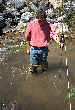
- The hydrographer should stand in a position that least affects the velocity
of the water passing the current meter. That position is usually obtained by
facing the bank so that the water flows against the side of the leg. The wading
rod is held at the tag line by the hydrographer who stands about 3 in (0.07 m)
downstream from the tag line and at least 1.5 ft (0.46 m) from the wading rod.
|
|
Correct position of a hydrographer with a wading rod. |
- The wading rod should be held in a vertical position with the meter parallel
to the direction of flow while the velocity is being observed.
|
- When measuring streams having shifting beds, the soundings or velocities can
be affected by the scoured depressions left by the hydrographer's feet. For such
streams, the meter should be placed ahead of and upstream from the feet.
|
|
Current-meter measurements from bridges |
- Bridges are often used for making discharge measurements of streams that
cannot be waded. Such measurements are often satisfactory, but cableway sections
are usually superior.
|
- Either the upstream or downstream side of the bridge can be used for making
a discharge measurement. The advantages of the upstream side are:
- Hydraulic characteristics at the upstream side of bridge openings usually
are more favorable.
- Approaching drift can be seen and thus can be more easily avoided.
- The streambed at the upstream side of the bridge is not likely to be scoured
as badly as the downstream side.
|
|
- The advantages of using the downstream side of the bridge are:
- Vertical angles are more easily measured because the sounding line will move
away from the bridge.
- The flow lines of the stream may be straightened by passing through a bridge
opening with piers.
|
|
- Whether to use the upstream side or the downstream side of a bridge for a
current-meter measurement should be decided individually for each bridge after
considering the above factors.
|
- Footbridges are sometimes used for measuring the discharge of canals,
tailraces, and small streams. Usually rod suspensions are used for the meter,
but hand lines, bridge cranes, and bridge boards can also be used.
|
|
Discharge measurement made from a footbridge with a 10-ft wading rod.
|
|
Measurement of Velocity |
- The current meter measures velocity at a point. The method of making
discharge measurements at a cross section requires determination of the mean
velocity in each of the selected verticals. The mean velocity in a vertical is
obtained from velocity observations at many points in that vertical, but it can
be approximated by making a few velocity observations and using a known relation
between those velocities and the mean in the vertical. The different methods of
determining mean
vertical velocity are described below. Flow velocity in natural channels
generally pulsates. Velocity is therefore measured for at least 40 seconds in an
effort to better represent average velocity at a point.
|
|
Two-point method |
- When velocity profiles are relatively normal, it has been found that average
velocity can be adequately estimated by averaging velocities at .2 and .8 of the
depth below the water surface.
- The vertical-velocity curve will be distorted by overhanging vegetation that
is in contact with the water or by submerged objects, if those elements are
close to the vertical in which velocity is being measured. In this case, an
additional velocity observation at 0.6 of the depth should be made.
- When a Price type AA (or type A) current meter is used, the two-point method
cannot be applied unless depths are greater than 2.5 ft (0.76 m).
|
|
Six-tenths-depth
method |
- In the 0.6-depth method, an observation of velocity made in the vertical at
0.6 of the depth below the surface is used as the mean velocity in the vertical.
This depth gives the nearest velocity to the mean velocity (see table 1 below,
after Rantz).
|
|
TABLE 1.- Coefficients for standard vertical velocity curve
| Ratio of observation
depth to depth of water in the vertical |
Ratio of point
velocity to mean velocity in the vertical |
| 0.05 |
1.16 |
| 0.1 |
1.16 |
| 0.2 |
1.149 |
| 0.3 |
1.13 |
| 0.4 |
1.108 |
| 0.5 |
1.067 |
| 0.6 |
1.02 |
| 0.7 |
0.953 |
| 0.8 |
0.871 |
| 0.9 |
0.746 |
| 0.95 |
0.648 |
Source: USGS with thanks
Calculation of Cross-sectional Area
-
Use our River Cross Section Creator and Calculator to quickly and accurately create a river cross section and calculate the cross sectional area, wetted perimeter and hydraulic radius. Multiplying the cross-sectional area by the average velocity will give the river discharge.
-
To manually calculate the cross-sectional area, use your raw data to draw the river cross-section(s) on graph paper. By maintaining the same scale for both the vertical and horizontal axes,
calculation of the wetted perimeter and cross-sectional area is simplified.
Either calculate the area of the smallest graph square (in m²)
and then count how many lie within the cross-section (part squares count as ½)
or divide the cross-section into a series of trapeziums and apply the formula
½(a+b)y to each trapezium, where a and b are the two parallel sides of unequal
length, and y the shortest side between them.
|